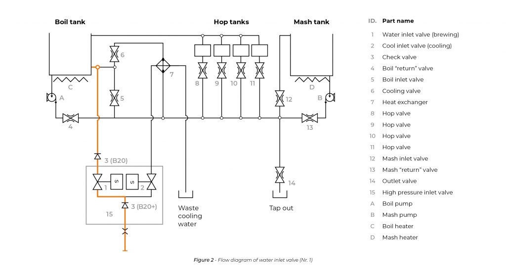
1. Automatic water inlet
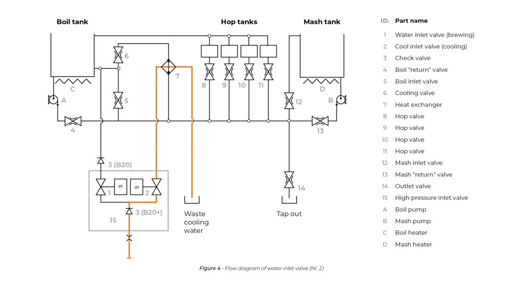
2. Testing the cooling cycle
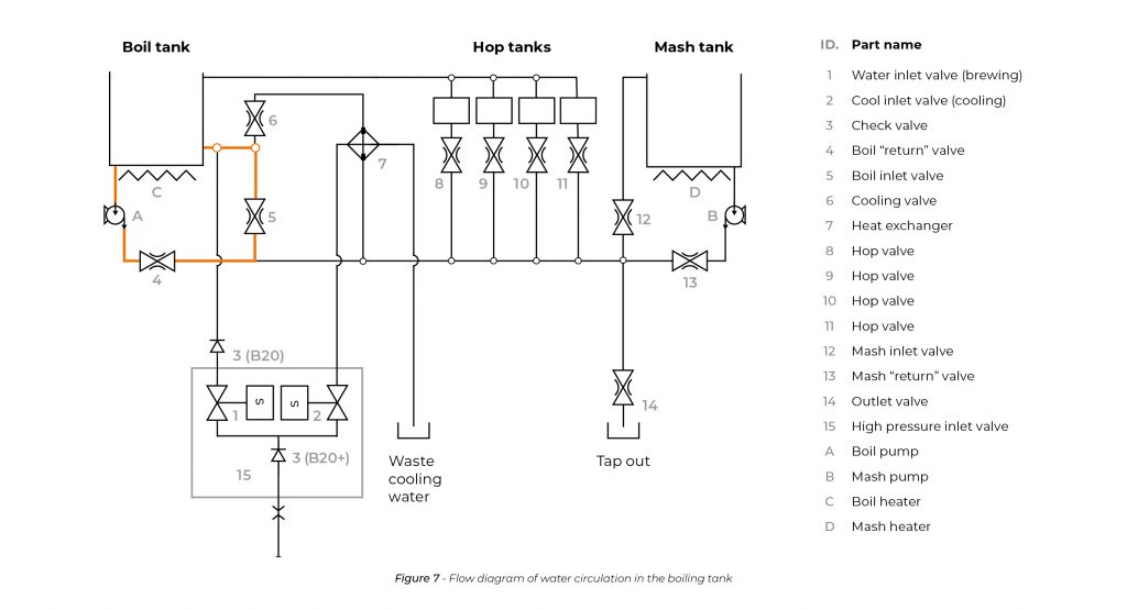
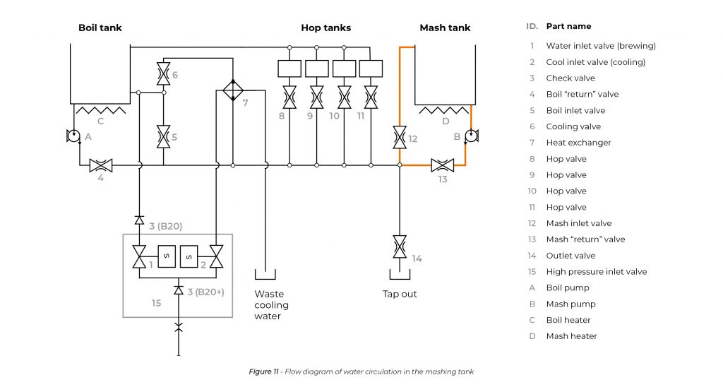
3. Water circulation on boiling side
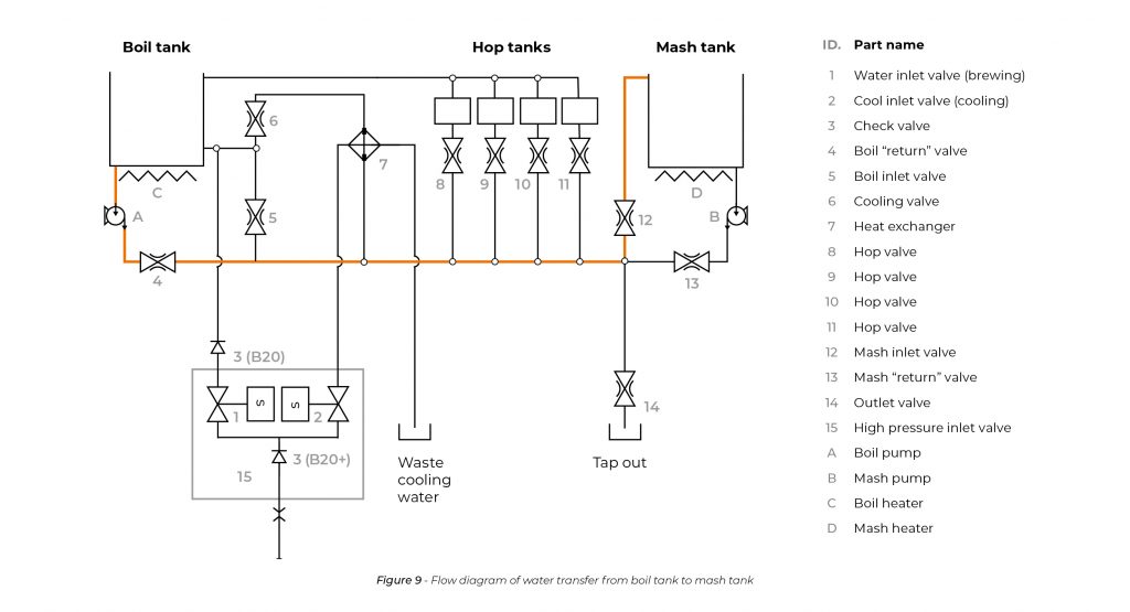
4. Water transfer to the mashing tank
5.Water circulation on mashing side
6. Detecting errors on both boiling and mashing sides
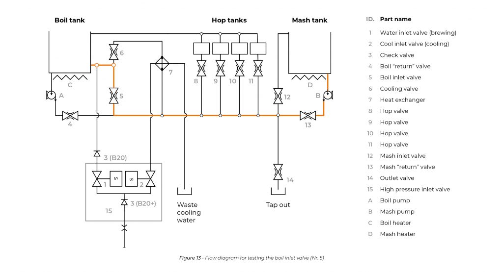
6.1 Testing the boiling inlet valve
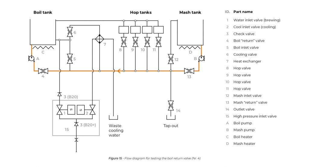
6.2 Testing the boiling non-return valve
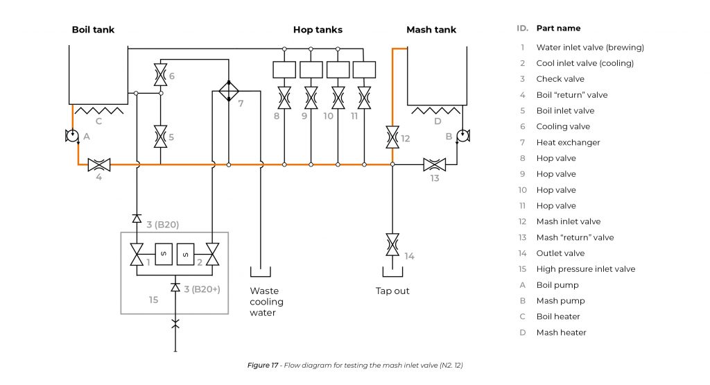
6.3 Testing the mashing inlet valve
6.4 Testing the mashing non-return valve
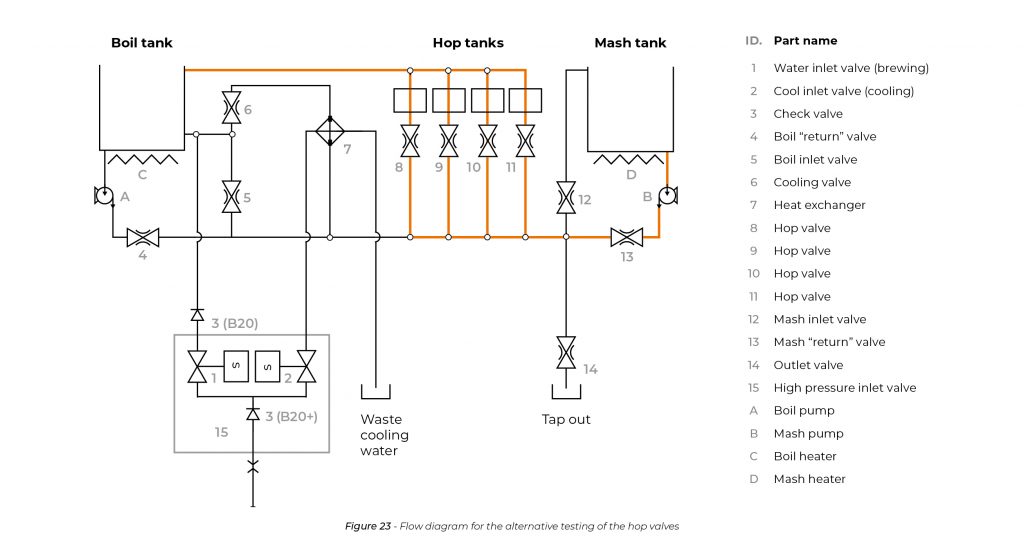
7. Testing the hop cages
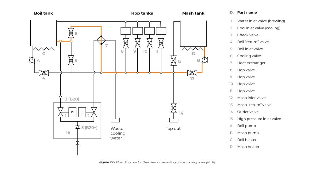
8.Testing the cooling valve
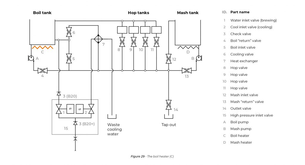
9. Boil heater
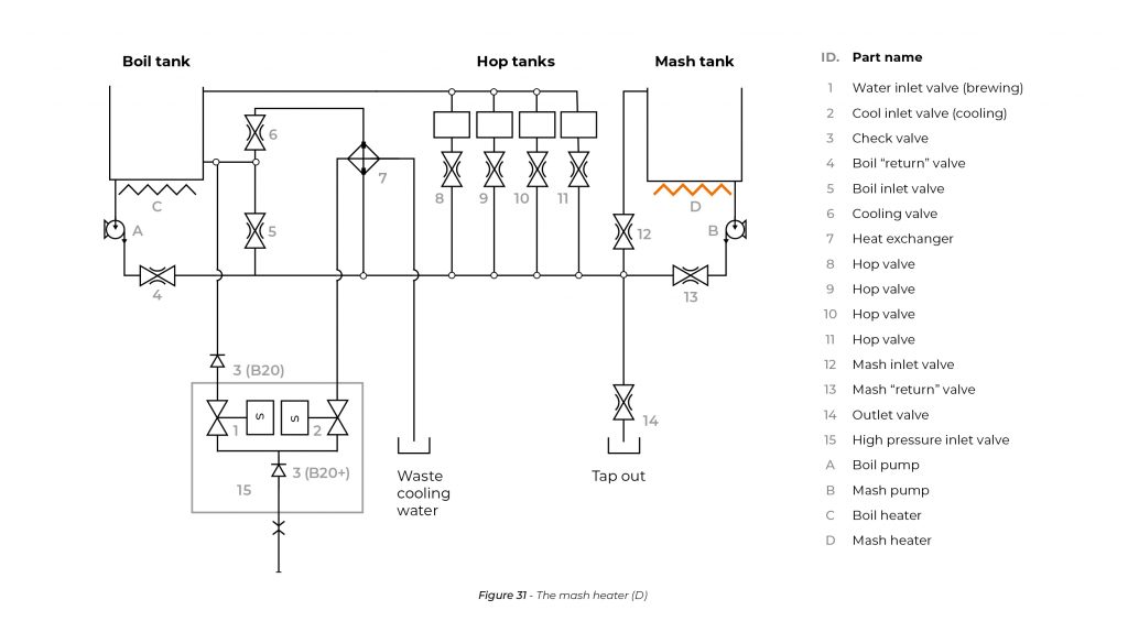
10. Mash heater
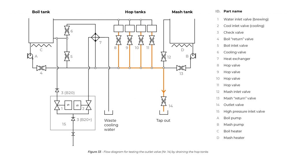
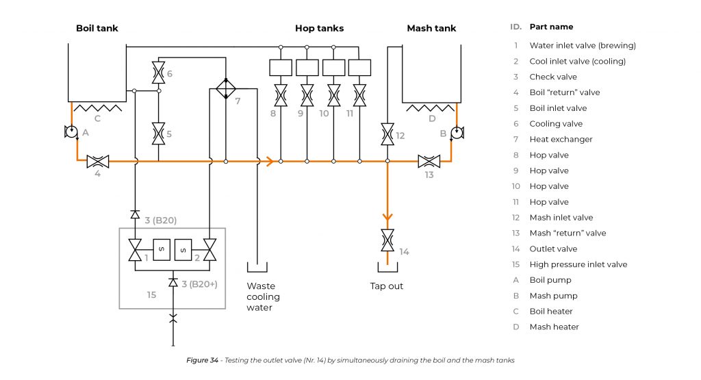
11. Draining